Raspberry Pi 4, 3 and Zero W Serial Port Usage
How configure the serial port on Raspberry Pi 4, 3+, 3, and Pi Zero W
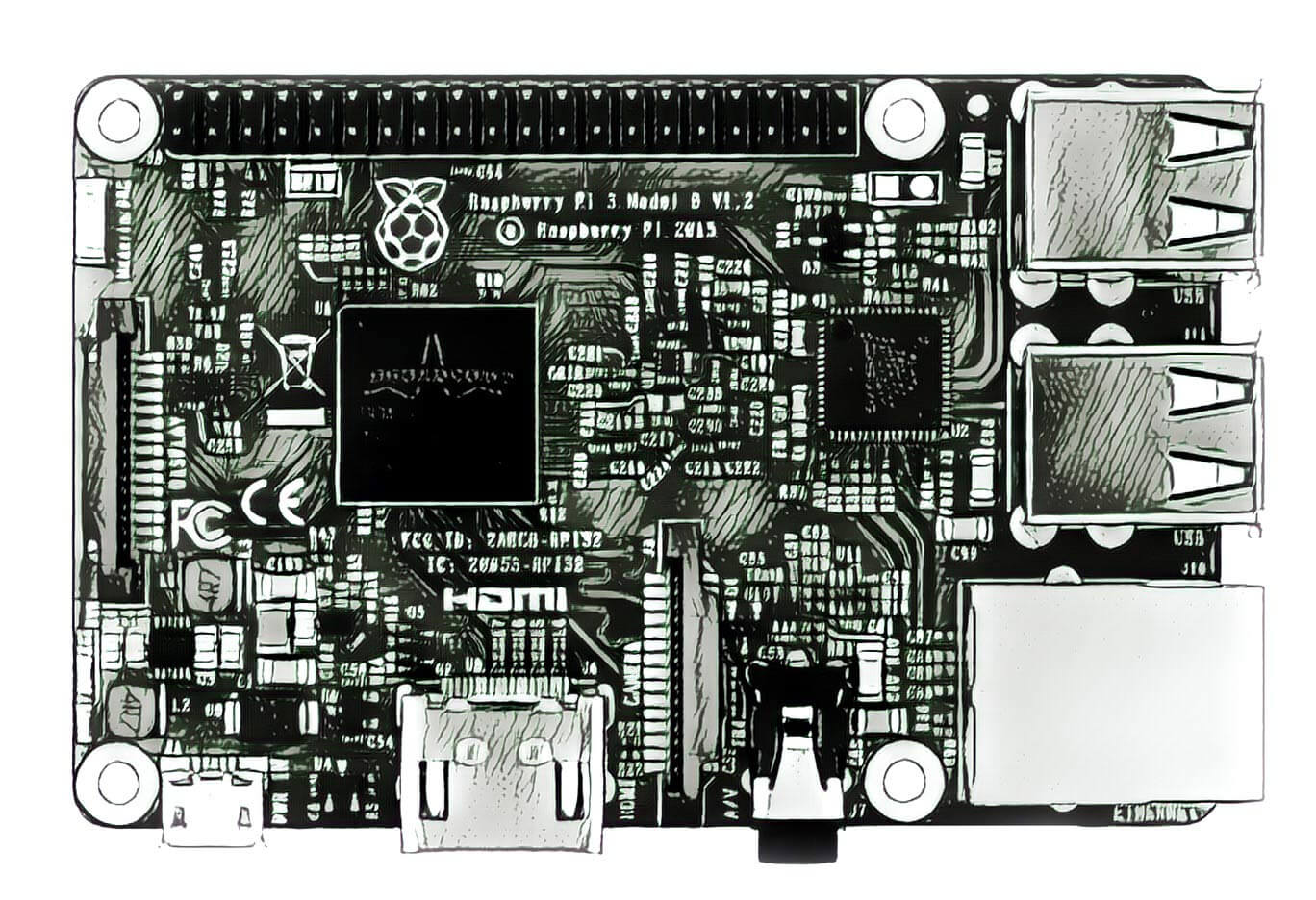
The Raspberry Pi 3, 4 serial port
The Raspberry Pi 3 Model B, B+, Pi Zero W contain two UART and Pi 4 four UART controllers which can be used for serial communication (more information here), the mini UART and PL011 UART. By default, the mini UART is mapped to the TXD (pin 8 / GPIO 14) and RXD (pin 10 / GPIO 15) on the 40 pin GPIO header and the PL011 UART is used for the Bluetooth/Wireless module but either module can be mapped to the GPIO port.

UART on the 40 pin GPIO PI header
The Raspberry Pi UARTs
A Universal Asynchronous Receiver-Transmitter (UART) is a computer hardware device for asynchronous serial communication in which the data format and transmission speeds are configurable. The electric signaling levels and methods are handled by a driver circuit external to the UART. A UART is usually an individual (or part of an) integrated circuit (IC) used for serial communications over a computer or peripheral device serial port. One or more UART peripherals are commonly integrated in microcontroller chips. A related device, the universal synchronous and asynchronous receiver-transmitter (USART) also supports synchronous operation. (Wikipedia)
UART0 = PL011
The Raspberry Pi SoC is still based on the same hardware, the BCM2835. Only the microprocessor has evolved. The BCM2835 has two UARTs for serial links. The first, PL011 is a “real” UART:
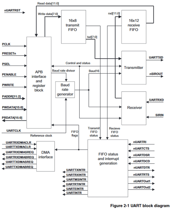
BCM2835 - UART block diagram
That is, it is autonomous, with its own Baud Rate generator, and all the circuits necessary for its operation.
UART1 = “mini” UART
The second UART is a “mini” UART:
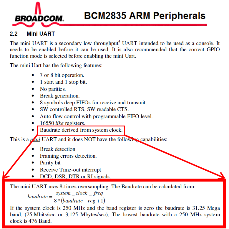
BCM2835 - mini UART baudrate
The “mini UART” port can be accessed using the /dev/ttyS0 device in Linux. One issue with the “mini UART” controller is that its baud rate is linked to the VPU core frequency so as the VPU frequency changes depending on processor load so does the baud rate of the UART controller. This will cause problems as serial devices expect a constant baud rate during communication.
To fix this issue the VPU core frequency must be fixed which can either limit the speed of the Raspberry Pi or increase power consumption and heat generated depending on what speed the core frequency is set at.
The mini UART controller has a smaller FIFO buffer than the PL011 UART controller. This can cause problems at higher baud rates as it makes losing characters more likely.
So
The PL011 UART controller is not linked to the VPU core frequency. This means that the baud rate stays the same regardless of VPU speed. The PL011 UART controller also includes other features not present in the mini UART controller such as framing error detection, break detection, receive timeout interrupts and parity bit support.
The main disadvantage of using the PL011 UART controller is that it disables the Bluetooth/Wireless module so you will be unable to use the Bluetooth features of the Raspberry Pi4, Pi3 and Zero W.
I recommend using the PL011 UART controller in any situation where a reliable data connection is needed, or power consumption and processor speed are a priority.
If you need to use the Bluetooth module on the Raspberry Pi, then you should use the mini UART controller.
Make a choise
The first thing to do is a choice. Do I need Bluetooth? My answer is no. This means that I can disable the Bluetooth and therefore recover the “Kivabian” UART.
You have 4 options
Option 1 : Using the real PL011 UART port
Use the UART (the real one!) by losing the Bluetooth function. You must swith the I/O of the two UARTs.
- Step 1 - Login via terminal or desktop and shell
- Step 2 - Device Tree settings as below:
Add device tree to /boot/config.txt to disable the bluetooth module.
sudo vi /boot/config.txt
Add at the end of the file for pi4
dtoverlay = disable-bt
Looking in /boot/overlays/README from the September 2019 release of Raspbian Buster I can now see disable-bt documented
- Step 3 - Exit the editor saving your changes and then:
sudo reboot
If everything is ok by doing an ls -l /dev/serial* you should find a serial0 port which points to ttyAMA0.

- Step 4 - Disabling the Serial Console (optional)
The serial console on Raspberry Pi Buster is enabled by default. To use the UART port with serial devices you will need to disable the console.
To disable the serial console, you need to edit the /boot/cmdline.txt file
sudo vi /boot/cmdline.txt
Find the following text and remove it:
console=serial0,115200
Exit the editor saving your changes and then:
sudo reboot
- Step 5 - Disabling bluetooth on raspberry
See post Disabling Bluetooth on Raspberry Pi.
With the serial console disabled you can now access the UART serial port at /dev/ttyAMA0. I chose this option.
Option 2 : Operate the serial interface and Bluetooth
The processor clock speed will be fixed (at a low speed [250MHz] or at a high speed [500MHz?]).
Add
enable_uart = 1to/boot/config.txtThis will affect processor performance as it controls the speed of the L2 cache, and there will also be a reduction in analog audio qualityIf you want high clock speed (you will really need a fan and a heatsink) to keep the processor performance and audio quality, also add
force_turbo = 1to/boot/config.txt
Option 3 : Correct Bluetooth with “rotten” serial interface
Having a “rotten” serial interface on the GPIO (variable speed) with having correct Bluetooth: Do nothing. These are the default settings
Option 4 : Correct serial interface (UART) with slowly Bluetooth
Operate the serial interface (UART) correctly, with a Bluetooth which operates slowly.
Add
dtoverlay = miniuart-btto the file/boot/config.txtSet the frequency to a fixed (low) value by adding, still to
/boot/config.txt:core_freq = 250. This will affect processor performance.
If you prefer to keep higher performance do not add the line core_freq = 250 but rather the line force_turbo = 1 (this requires using a fan and a radiator).
How to test the configuration
Before to connect anything to the serial port, we must test at first if it works. Connect the GPIO 14 (pin 8) and GPIO 15 (pin 10) corresponding to TxD (data sent) and RxD (data received). When you are going to send data to the TxD serial port, they will come back through the RxD port … (loopback)! And the program used to send the data will receive it and display it.

Loopback UART on the 40 pin GPIO PI header
Connect pin 8 and pin 10 with a resistor to avoid destroying the ports (or worse) in the event of an error. 680 Ω or 560 Ω will do it well.
The loopback works well when the UART is connected to pins 8 and 10. Remember to disconnect the short-circuit between these two pin after the end of the tests, otherwise you risk damaging your SoC!
Python script for test
#!/usr/bin/env python
# -*- coding: utf-8 -*-
import serial
test_string = "Test serial port ...".encode('utf-8')
port_list = ["/dev/ttyAMA0","/dev/ttyAMA0","/dev/ttyS0","/dev/ttyS"]
for port in port_list:
  try:
    serialPort = serial.Serial(port, 9600, timeout = 2)
    print ("Serial port", port, " ready for test :")
    bytes_sent = serialPort.write(test_string)
    print ("Sended", bytes_sent, "byte")
    loopback = serialPort.read(bytes_sent)
    if loopback == test_string:
      print ("Received ",len(loopback), "bytes. Port", port,"is OK ! \n")
    else:
      print ("Received incorrect data:", loopback, "on serial part", port, "loopback \n")
    serialPort.close()
  except IOError:
    print ("Error on", port,"\n")
serial_uart_test_TxRx.py
This program will send data as output to the serial port, then retrieve it from the input. Here the test that interests us is that of /dev/ttyAMA0.
- Start the test program and you should get:
$ python serial_uart_test_TxRx.py
Serial port /dev/ttyAMA0 ready for test :
Sended 33 bytes
Received 33 bytes. Port /dev/ttyAMA0 is OK !
Serial port /dev/ttyAMA0 ready for test :
Sended 33 bytes
Received 33 bytes. Port /dev/ttyAMA0 is OK !
If you do not have confirmation that the ttyAMA0 port is working correctly, no need to continue. You must first operate this port to use it.