Raspberry PI powered over Ethernet (PoE)
- PoE Raspberry Pi compatibility
- RaspberryPi 4 J14 connector
- IEEE 802.3af-2003 PoE
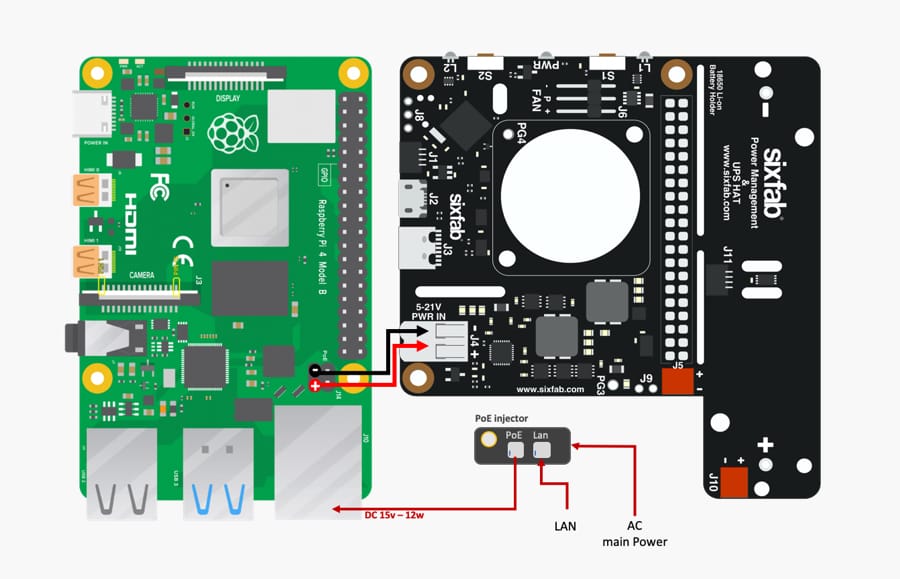
- Connecte Pi PoE Header to Sixfab Power Managemen board
PoE Raspberry Pi compatibility
The Raspberry Pi 4 uses a Trxcom TRJG0926HENL RJ45 connector. It design to support application, sush as ADSL modem, LAN-on-Motherboard (LOM), hub and switch.
However, if you have a proper 802.3af injector you can retrieve the injected power.
The PoE require a new 4-pin connector (J14) on the 3B+ board however and later devices, red arrow here:
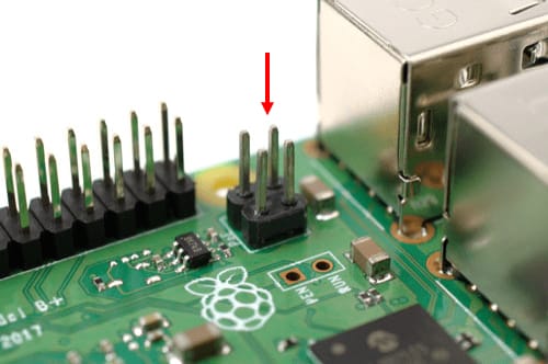
RaspberryPi 4 J14 connector
I have tested the POE connector with a multimeter, as I expected each pin on the POE header corresponds to a pair on the Ethernet connector. I include a picture below of the pin mapping I have determined.
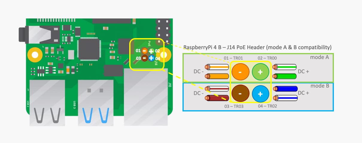
Note : The Raspberry Pi does not work with PoE wirings where two pairs are used for 10/100BaseT and two pairs are used for power. It needs all 8 wires connected.
IEEE 802.3af-2003 PoE
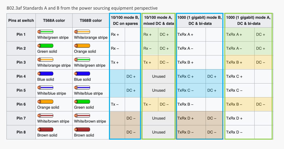
Mode A has two alternate configurations (MDI and MDI-X), using the same pairs but with different polarities. In mode A, pins 1 and 2 (pair #2 in T568B wiring) form one side of the 48 V DC, and pins 3 and 6 (pair #3 in T568B) form the other side. These are the same two pairs used for data transmission in 10BASE-T and 100BASE-TX, allowing the provision of both power and data over only two pairs in such networks. The free polarity allows PoE to accommodate for crossover cables, patch cables and Auto MDI-X.
In mode B, pins 4–5 (pair #1 in both T568A and T568B) form one side of the DC supply and pins 7–8 (pair #4 in both T568A and T568B) provide the return; these are the “spare” pairs in 10BASE-T and 100BASE-TX. Mode B, therefore, requires a 4-pair cable.
Connecte Pi PoE Header to Sixfab Power Managemen board
Many ethernet ports on devices not intended to be PoE powered terminate the connection in ways that will draw power anyway, possibly damaging the devices. This is often due to the fact that PoE didn’t exist when many ethernet deices were first built, and many devices still make no allowance for this.
With 802.3af/at, PoE the powering device tries to determine if the device plugged into it needs power or not, and this usually works OK.
But with passive PoE, the power is just there (often controlled by managing the device) and can damage things not expecting power to be there. So the Ethernet port of the Raspberry PI 3B+ and 4B not intended to be PoE 15V powered terminate the connection.
So you must force the ethernet interface to 100Mbit in full duplex and with autoneg attribute to off. This allows you to force the configuration of the RaspberryPi ethernet interface without dialog with the source interface.
You can do this with this commande : ethtool -s eth0 speed 100 duplex full autoneg off
If you want to persist this at reboot of your system, you can and this line in /etc/rc.local file.
#!/bin/sh -e
#
# rc.local
#

/sbin/ethtool -s eth0 autoneg off speed 100 duplex full

exit 0
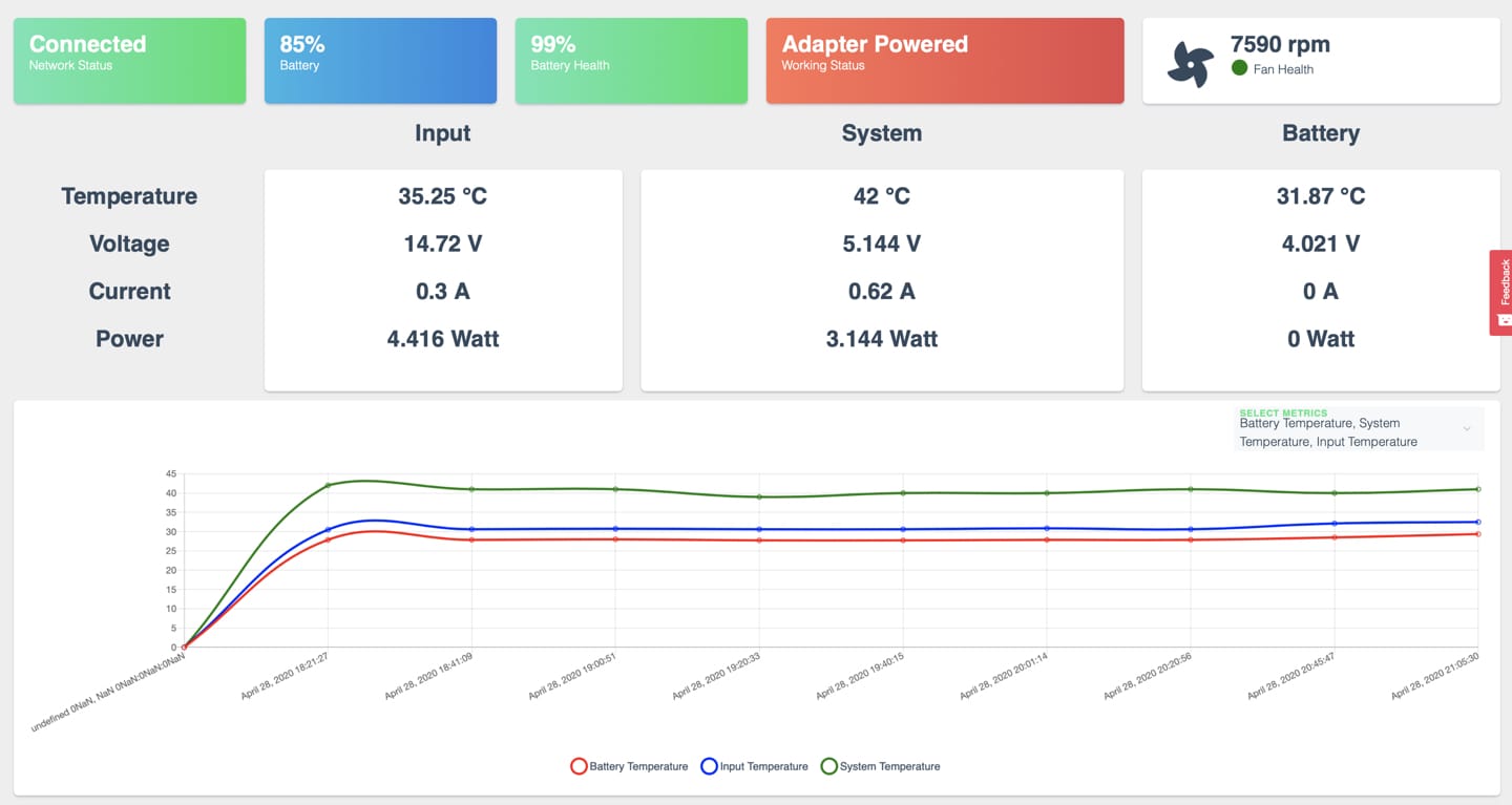
Now, the eth0 interface is UP, and the PoE injector power supply the Sixfab Power Management & UPS HAT by his 3.9v-21v DC input connector power input connector.
Note : The “Sixfab Power Management & UPS HAT”
J4external power input must be powered with SMD terminal Block 3.9V to 21V. So you must have a PoE injector who this respected DC voltage input exigence.