Raspberry Pi - Sixfab 3G/4G & LTE Base HAT
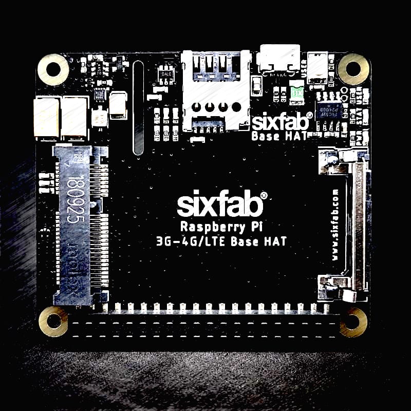
The Sixfab 3G/4G & LTE Base HAT grants your Raspberry Pi or 40-pin Pi compatible single-board-computer a super-simple interface bridge between mini PCIe cellular modems. With the modems you insert into Base HAT, your Raspberry Pi based projects will access data networks all around the world.
Sixfab®
Wednesday 15 July 2020
- Description
- Features
- Base HAT vs Base Shield V2
- Migration to Base HAT from Base Shield V2
- Key Applications
- Hardware Prerequisites
- Hardware setup
- Technical Details
Description
The Sixfab 3G/4G & LTE Base HAT grants your Raspberry Pi or 40-pin Pi compatible single-board-computer a super-simple interface bridge between mini PCIe cellular modems. With the modems you insert into Base HAT, your Raspberry Pi based projects will access data networks all around the world. This Base HAT enables high-bandwidth cellular connectivity on your remote devices. From low-power consumption LTE-M to ultra-high-speed LTE-Advanced mini PCIe cards supported by this HAT. Both UART and USB communication with modules is available on the shield.
Remote management of your devices on the field, secure connection over the mobile network, reliable coverage across the globe with lots of carrier option is available with this HAT stacked on the Raspberry Pi. It can be used as an LTE modem or dongle. If you’re looking for a Raspberry Pi LTE HAT for applications like Raspberry Pi video streaming or high-speed data transferring, you are at right place. Making a remote controllable LTE Wi-Fi Hotspot, high-speed `GPSv tracking, more and more use case is possible with his add-on board.
Features
- Fully compatible with
Raspberry Pimodels that have the 40-pinGPIOheader (4, 3, 2, B+, A+, Zero) - Easy-to-use, simple setup, plug-and-play
QMIandPPPare supported (QMIis recommended)- Clip-in
Mini PCIesocket compatible with worldwideLTE,UMTS/HSPA+andGSM/GPRS/EDGEcoverage with regional or global modules which work with different frequencies & carriers - With the
4G/LTEModule (e.gQuectel EC25) you can reach 150Mbps downlink and 50Mbps uplink data rates. And the 3G Module( e.gQuectel UC20) delivers the maximum data rate of 14.4Mbps downlink and 5.76Mbps uplink. - Micro SIM Card socket can easily reachable on the upside of the HAT.
- Can be used standalone with PC/Laptop over
micro USB, without stacking withRaspberry Pi. - The HAT can be powered from an external 5V source by exposed power pins, directly from
Raspberry Pi5VGPIOheaders, viamicro USB, or optionalJSTconnector on the bottom of the board. A specially designed 90-degree right anglemicro USBcable is included to package. - Efficient and low quiescent current power circuit can hold up to 3Amps
- Optional Send/Receive AT commands over
Raspberry PiUARTport is available - Taking the module into the Airplane Mode, resetting module or RI and DTR functions can be accessible over
GPIOpins. - The power of the whole board electronics can be disabled for low-power consumption use cases
- The modules(
EC25&UC20) have built-inGNSS(GPS/GLONASS)receiver for your location-based applications. - Working temperature range: -40°C ~ 80°C
Base HAT vs Base Shield V2
- Base HAT does not require to choose its header type, long, short or no header. It comes with an SMD header acceptable and short&long headers, you can stack it whatever you want.
- You can completely disconnect the power of HAT by driving
GPIO26to a HIGH-level voltage state. Then it starts to consume below 1 milliamp typically. - USER LED is added and light up if you drive
GPIO27to HIGH. - USER BUTTON added and pulled-up by default. When you push the button, you can sense a LOW level from
GPIO22. - Now, it can be called as a HAT not shield, complies with HAT requirements by Raspberry Pi Foundation.
- It has a slot for Pi Camera on board for easy mount.
- The location of the micro USB connector realigned. It is better now to use the right-angle
micro USBcable included in the package without bending it too much. - There is a new footprint for a surface mount right-angle JST connector on the bottom of the board for external 5V sources. It is not soldered by default.
- All
GPIOpins used by HAT connected to Raspberry Pi IOs via normally-close jumpers. You can easily cut the connection on the bottom of the board if the pin occupied by another HAT you stacked on it.
Migration to Base HAT from Base Shield V2
The new HAT has better power circuitry and features than Base Shield V2. It is pin-to-pin compatible, your old setup will work with the new Base HAT right out of the box. You need only check the following points:
- On the Base Shield V2 the
GPIO26connected to PERST-PCI pin of the miniPCI pinout. It lets you reset the modem by changing the state of this pin. Now, this pin used for enabling/disabling of the power of HAT, that means you can reset the modem by cutting its power and enabling then. - Two new IO pins,
GPIO27andGPIO22populated by USER LED and BUTTON respectively by this new HAT. If you need these pins by your project, you can cut the jumpers on the bottom of the board easily. (SJ5for the button,SJ6for LED)
Key Applications
- Video/Music Streaming
- Large Data Downloads and Uploads
- LTE Router
- Mobile Internet Hotspot
- High-speed GPS Tracking
- Real-time Environmental Monitoring
- Smart City & Agriculture Applications
- Smart Parking
- Security & Asset tracking
Hardware Prerequisites
- Raspberry Pi
- 3G/4G & LTE Base HAT
- LTE – GNSS Dual u.FL Antenna – 100mm
- LTE Full Band PCB Antenna – u.FL Plug – 100mm
- Quectel EC25 Mini PCle 4G/LTE Module (or other compatible LTE Modules)
Hardware setup
- Attach the EC25 module to the HAT
- Attach the antenna to the module, nsert your SIM card into HAT
- Insert your SIM card into HAT.
- Attach the HAT to the Raspberry Pi
- Connect the Micro-USB cable to the HAT and Raspberry Pi
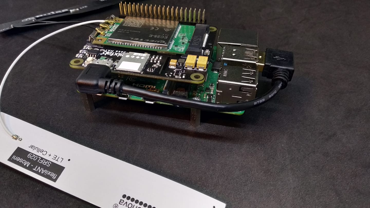
Hardware setup sample
Technical Details
Pinout
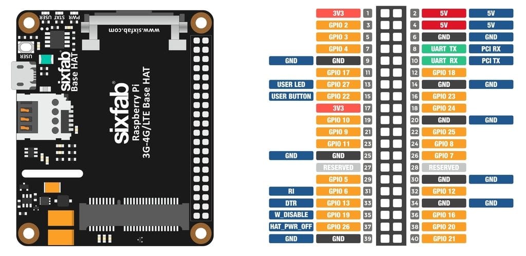
Sixfab LTE base HAT Pinout
Pin Descriptions
| Pin Number | BCM Pin | Pin Name | Description |
|---|---|---|---|
| 8 | UART_TX | PCI RX | This pin functions as the serial data input to the module for UART communication |
| 10 | UART_RX | PCI TX | This pin functions as the serial data output from the module for UART communication |
| 13 | GPIO27 | USER LED | Active HIGH, to switch on the USER LED, the pin’s state should be HIGH |
| 15 | GPIO22 | USER BUTTON | This pin normally pulled-down to ground. When the button is pressed, pin switches to LOW |
| 31 | GPIO6 | RI | This pin is Ring indicator functions as the indication for receiving call or SMS, can be calibrated to HIGH or LOW using the AT commands |
| 33 | GPIO13 | DTR | When the module is in sleep mode, DTR pin allows to wake up the module up by pulling it to LOW |
| 35 | GPIO19 | W_DISABLE | This pin is used to turn Airplane Mode on the module, by pulling it HIGH |
| 37 | GPIO26 | HAT_PWR_OFF | Power regulator control. Normally pulled-down, when this pin drove to HIGH, Hat’s power will cut off |
Layout
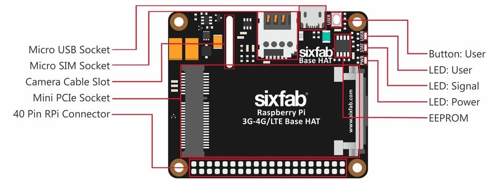
Sixfab LTE base HAT Layout
Schematics
You can download the schematic of Base HAT from here
Compatible Mini PCIe Modules
- Quectel:
- EC25 Mini PCIe 4G IoT Module (EC25 & EC21 AT Commands Manual)
- EC21 Mini PCIe 4G IoT Module
- EC20 Mini PCIe 4G IoT Module
- UC20 Mini PCIe 3G IoT Module
- LTE-EP06
- Sierra
- AirPrime MC Series
- Telit
- LM960, LE910V2, HE910, LE910Cx, and more
- Huawei
- ME909s-120, ME909s-821, and more
- Simcom
- SIM7100, SIM7230, and more
- ZTE
- ZM8620, and more
- U-Blox
- MPCI-L2 Series
If one is looking to use different mini PCIe modules other than the ones mentioned above, it should be compared with the pinout of mini PCIe below. The following mentioned pins are connected to the Base HAT.
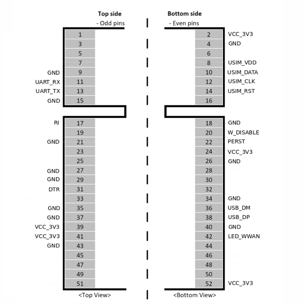
Mini PCIe connected pins to Base HAT
Compatible Boards
- Raspberry Pi 4, 3, 2, B+, A+, Zero i.e. RPi which contains 40W
GPIOheader. - Asus Tinker Board
- Rock 64*
- Orange Pi*
- Samsung ARTIK’s Eagleye board*
- Latte Panda
For the best working condition, power the Raspberry Pi with a minimum 2 Amps 5V adapter while using the Base HAT attached. We don’t recommend the usage of long and low-quality micro USB cables between Base Shield and Raspberry Pi. It causes data and power loss. Thus, the cable included the package works greatly.
Dimension
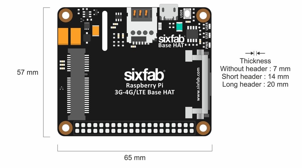
Sixfab LTE base HAT Dimension
LEDs
- PWR LED : When the module is powered up, this RED led turns on
- SGNL LED : This BLUE led indicates the status of the connection. When the connection is established and data is being transmitted/received, this led will blink at special intervals. Otherwise, if there is no connection, the led will remain off.
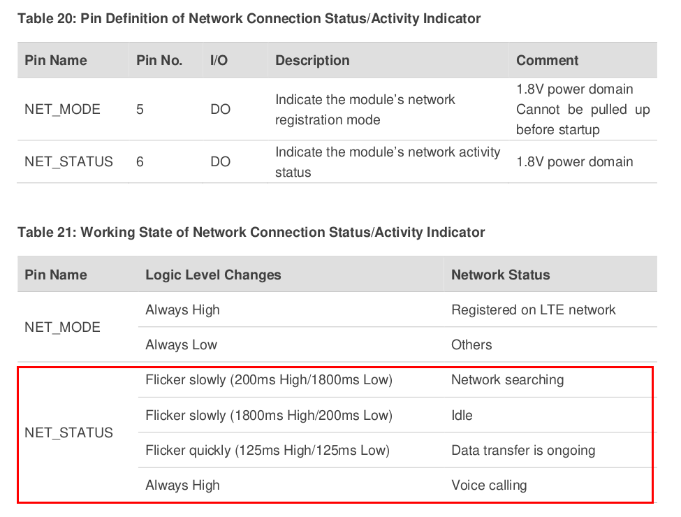
Sixfab LTE base HAT LED status
- USER LED : It is a programmable user-led can be controlled from the
GPIO27ofRaspberry Pifor debugging or just fun.
Buttons
- User Button : It is a programmable user button that is connected to
GPIO22. Reads by default
Solder Jumper(SJ)
When you observe the HAT, you will come across some solder Jumpers marked as SJx (SJ1, SJ2, SJ3 etc)
These solder jumpers are either connected or disconnected by default. These can be used to enable or disable the default use case. These SJ are provided for the cases where the specific GPIO are conflicting with the users requirement. Disconnecting the jumpers may lead to loss in some programmable feature. For instance, Cutting the SJ4 trace which is RI, Ring Indicator used as indication for call or SMS cannot be used.
Disconnecting
Cut the narrow trace between the middle of these solder jumper with a utility knife.
Connecting/Reconnecting
Solder the jumper to connect the traces.
| Solder Jumper | Corresponding GPIO | Default State | Purpose | Affect of changing the default state |
|---|---|---|---|---|
| SJ1 | GPIO26 | CONNECTED | Cut to disconnect from HAT_PWR_OFF | Cannot control the power of the HAT |
| SJ2 | GPIO19 | CONNECTED | Cut to disconnect from W_DISABLE | Cannot disable Wireless communication |
| SJ3 | GPIO13 | CONNECTED | Cut to disconnect DTR pin from GPIO | Cannot use for sleep mode control |
| SJ4 | GPIO6 | CONNECTED | Cut to disconnect RI pin from GPIO | Cannot read the Ring indicator |
| SJ5 | GPIO22 | CONNECTED | Cut to disconnect USER LED | Cannot use User Led |
| SJ6 | GPIO27 | CONNECTED | Cut to disconnect USER BUTTON | Cannot use User Button |
| SJ7 | RXD | NOT CONNECTED | Solder to connect RX of module. Used to communicate over UART | - |
| SJ8 | TXD | NOT CONNECTED | Solder to connect TX of module. Used to communicate over UART | - |


